Cisco PT 案例九:单臂路由
单臂路由(router-on-a-stick)是指在路由器的一个接口上通过配置子接口(或“逻辑接口”,并不存在真正物理接口)的方式,实现原来相互隔离的不同VLAN(虚拟局域网)之间的互联互通。
环境
- Cisco Packet Tracer 5.3
- Windows 10
## 操作
操作:按照如图所示连接拓扑图
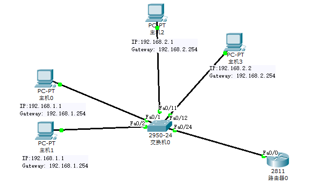
image.png
添加一台路由器、一台交换机和四台主机
PC0和PC1与交换机fa0/1、fa0/2 接口连接,划分在VLAN10中,IP分别为192.168.10.1、192.168.10.2,网关192.168.10.254。
PC2和PC3与交换机fa0/11、fa0/12 接口连接,划分在VLAN20中,IP分别为192.168.20.1、192.168.20.2,网关192.168.20.254。
交换机fa0/24端口与路由器fa0/1端口连接。
(2)配置交换机 ```bash / Part 1 配置交换机 / Switch>enable Switch#configure terminal Switch(config)#hostname SA SA(config)#vlan 10 SA(config-vlan)#vlan 20 SA(config-vlan)#exit SA(config)#interface range fa0/1-fa0/2 SA(config-if-range)#switchport access vlan 10 SA(config-if-range)#interface range fa0/11-fa0/12 SA(config-if-range)#switchport access vlan 20 SA(config-if-range)#interface fa0/24 SA(config-if)#switchport mode trunk SA(config-if)#switchport trunk allowed vlan all
/ Part 2 检查配置 / SA(config-if-range)#^Z (Ctrl+Z组合键) SA#show vlan ... VLAN Name Status Ports ---- -------------------------------- --------- ------------------------------- 1 default active Fa0/3, Fa0/4, Fa0/5, Fa0/6
Fa0/7, Fa0/8, Fa0/9, Fa0/10
Fa0/13, Fa0/14, Fa0/15, Fa0/16
Fa0/17, Fa0/18, Fa0/19, Fa0/20
Fa0/21, Fa0/22, Fa0/23
10 VLAN0010 active Fa0/1, Fa0/2 20 VLAN0020 active Fa0/11, Fa0/12 ...
(3)配置路由器
bash / Part 1 配置路由器 / Router>enable Router#configure terminal Router(config)#hostname RA RA(config)#interface fa0/0.1 RA(config-subif)#encapsulation dot1Q 10 // (1:在路由器上配置trunk的封装协议的命令: // encapsulation [isl/dot1q] vlan# // 2:上面的路由器配置了dot1q中继封装,10是vlan 10。 // 3:Trunk的封装类型一共有 ISL和802.1Q两种,而802.1Q在输入的时候为dot1q) RA(config-subif)#ip address 192.168.10.254 255.255.255.0 RA(config-subif)#interface fa0/0.2 RA(config-subif)#encapsulation dot1Q 20 RA(config-subif)#ip address 192.168.20.254 255.255.255.0 RA(config-subif)#exit RA(config)#interface fa0/0 RA(config-if)#shutdown RA(config-if)#no shutdown //(重启fa0/0接口)
/ Part 2 检查配置 / RA>show interfaces fa0/0.1 ... Internet address is 192.168.1.254/24 ... Encapsulation 802.1Q Virtual LAN, Vlan ID 10 ...
RA>show interfaces fa0/0.2 ... Internet address is 192.168.2.254/24 ... Encapsulation 802.1Q Virtual LAN, Vlan ID 20 ...
(4)连通性测试
bash / Part 1 PC0 Ping 自己网关 / PC>ping 192.168.1.254
Pinging 192.168.1.254 with 32 bytes of data:
Reply from 192.168.1.254: bytes=32 time=11ms TTL=255 Reply from 192.168.1.254: bytes=32 time=12ms TTL=255 Reply from 192.168.1.254: bytes=32 time=11ms TTL=255 Reply from 192.168.1.254: bytes=32 time=12ms TTL=255
Ping statistics for 192.168.1.254:
Packets: Sent = 4, Received = 4, Lost = 0 (0% loss),Approximate round trip times in milli-seconds:
Minimum = 11ms, Maximum = 12ms, Average = 11ms/ Part 2 PC0 Ping PC1 / PC>ping 192.168.1.2
Pinging 192.168.1.2 with 32 bytes of data:
Reply from 192.168.1.2: bytes=32 time=25ms TTL=128 Reply from 192.168.1.2: bytes=32 time=10ms TTL=128 Reply from 192.168.1.2: bytes=32 time=12ms TTL=128 Reply from 192.168.1.2: bytes=32 time=14ms TTL=128
Ping statistics for 192.168.1.2:
Packets: Sent = 4, Received = 4, Lost = 0 (0% loss),Approximate round trip times in milli-seconds:
Minimum = 10ms, Maximum = 25ms, Average = 15ms/ Part 3 PC0 Ping PC2 PC3网关 / PC>ping 192.168.2.254
Pinging 192.168.2.254 with 32 bytes of data:
Reply from 192.168.2.254: bytes=32 time=11ms TTL=255 Reply from 192.168.2.254: bytes=32 time=14ms TTL=255 Reply from 192.168.2.254: bytes=32 time=11ms TTL=255 Reply from 192.168.2.254: bytes=32 time=12ms TTL=255
Ping statistics for 192.168.2.254:
Packets: Sent = 4, Received = 4, Lost = 0 (0% loss),Approximate round trip times in milli-seconds:
Minimum = 11ms, Maximum = 14ms, Average = 12ms/ Part 4 PC0 Ping PC2 / PC>ping 192.168.2.1
Pinging 192.168.2.1 with 32 bytes of data:
Reply from 192.168.2.1: bytes=32 time=24ms TTL=127 Reply from 192.168.2.1: bytes=32 time=19ms TTL=127 Reply from 192.168.2.1: bytes=32 time=21ms TTL=127 Reply from 192.168.2.1: bytes=32 time=20ms TTL=127
Ping statistics for 192.168.2.1:
Packets: Sent = 4, Received = 4, Lost = 0 (0% loss),Approximate round trip times in milli-seconds:
Minimum = 19ms, Maximum = 24ms, Average = 21ms/ Part 5 PC0 Ping PC3 / PC>ping 192.168.2.2
Pinging 192.168.2.2 with 32 bytes of data:
Request timed out. Reply from 192.168.2.2: bytes=32 time=24ms TTL=127 Reply from 192.168.2.2: bytes=32 time=22ms TTL=127 Reply from 192.168.2.2: bytes=32 time=19ms TTL=127
Ping statistics for 192.168.2.2:
Packets: Sent = 4, Received = 3, Lost = 1 (25% loss),Approximate round trip times in milli-seconds:
Minimum = 19ms, Maximum = 24ms, Average = 21ms<a name="F1D2o"></a>
## 结论
由实验可知,划分VLAN后不同VLAN间的主机不能通信,可以使用路由器进行VLAN间通信。
> 注意:
> 1、主机需要配网关。
> 2、当出现Ping不通别的主机时,可以采用由近及远的检查方式,即依次Ping自己、自己的网关、对方主机的网关、对方主机以便于发现错误位置。
<a name="qhjTr"></a>
## 实验工程
[单臂路由.zip](https://www.yuque.com/attachments/yuque/0/2020/zip/376635/1592556866521-6c52a943-bad3-4354-bbac-ab126434a011.zip?_lake_card=%7B%22status%22%3A%22done%22%2C%22source%22%3A%22transfer%22%2C%22src%22%3A%22https%3A%2F%2Fwww.yuque.com%2Fattachments%2Fyuque%2F0%2F2020%2Fzip%2F376635%2F1592556866521-6c52a943-bad3-4354-bbac-ab126434a011.zip%22%2C%22name%22%3A%22%E5%8D%95%E8%87%82%E8%B7%AF%E7%94%B1.zip%22%2C%22ext%22%3A%22zip%22%2C%22size%22%3A6937%2C%22id%22%3A%22gJ8dJ%22%2C%22card%22%3A%22file%22%7D)